Bring Images to Life: Image-editing software, an ink-jet
printer and
transparency film can create microscope filters for a dark-field imaging technique.
by Michael R. Peres and Joseph Cowan
Making photographs at the microscope can be difficult. For example, magnification
produces problems associated with the depth of field, and diffraction creates
problems with image resolution.
One of the most difficult aspects of photographing through a microscope is creating
image contrast, especially with thin, nearly transparent subjects. An early solution
was the implementation of dark-field illumination, which involves using oblique-angle
lighting from outside the lens’s field of view. In this method, a white
subject appears in front of a black background because light refracts to the lens
from the subject.
In 1896, Julius Rheinberg published a paper in the Journal of the Royal Microscopical
Society that described a method for optically coloring a subject’s features
using a microscope. The technique, now called Rheinberg differential color illumination,
used concepts inherent to dark-field illumination methods and some of Ernst Abbe’s
optical theories.
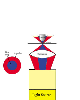
The premise of the technique was simple (Figure 2):

This disc stop that typically is used in dark-field techniques to subtract the
background illumination would be replaced by a dense, colored disc. The usually
clear region that surrounds the illumination system (the annulus) would be replaced
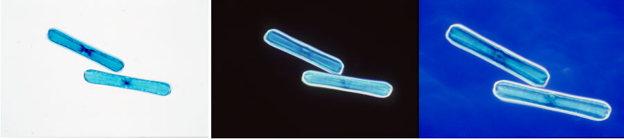
with a lightly colored annulus. The effects that Rheinberg illumination can produce
are very attractive and create interest in subjects that are otherwise monochromatic
and bland (Figure 3).
Early methods of producing the required filters were slow and labor-intensive.
As technology has improved, new ways to create the Rheinberg filters have evolved.
The intent of our project was to explore more efficient and accurate methods of
producing these filters using digital imaging technology. We have found that using
a standard microscope, a 10x objective and a Abbe or swing-out condenser, a person
with access to imaging-editing software and a desktop printer can easily create
many variations of Rheinberg filters and illumination.
Determining Their Size
Before creating the filters, the user must precisely measure various aspects of
the microscope. The numerical aperture (NA) of the substage condenser must be
determined for each objective that Rheinberg illumination will be used with. The
higher the NA of the objective, the greater the disc stop that will be required.
Abbe condensers provide the best access to the aperture diaphragm, which is where
the filters must be placed. The following steps worked well:
1. Establish Köhler illumination with a slide (the sample is insignificant)
at the subject stage.
2. With the objective in place, close the aperture diaphragm.
3. Remove one eyepiece.
4. Looking down the body tube of the microscope, open the aperture diaphragm until
it leaves just the field of view.
5. Without disturbing the aperture diaphragm, remove the substage condenser.
6. Turn the condenser over and use a vernier caliper to measure the diameter of
the aperture diaphragm’s opening blades. Record this number, which is the
diameter of the disc stop for that objective.
7. Replace the condenser and repeat the entire process for any objectives where
Rheinberg illumination would be desirable.
8. To find the full diameter of a filter, open the blades of the aperture diaphragm
all the way and measure the total diameter of the opening.
Making the Files
To create your filters, open your favorite photo editing or illustration software:
e.g. Adobe Photoshop or Illustrator, or Macromedia Freehand. Create a square image
file with dimensions equal to the total diameter of the filter from Step 8 above.
Using a black 1-pixel line, draw a circle that exactly fits, centered, inside
that square. Still using a black 1-pixel line, draw another circle whose diameter
equals the diameter of the disc stop from Step 6 above. Save this image as a template
that you can use whenever you want a new filter for the measured objective.
The template will help you make a sheet of several filters. There are two basic
ways to design the filters. The first is to create one filter with different colors
on the disc stop and the annulus. The advantages to this are ease of use at the
microscope and improved optical quality because the light passes through only
one filter. The other way is to produce one filter for the disc stop and one for
the annulus. The advantage to this approach is a higher degree of variability
because they can be mixed and matched for different experiments.
Create a blank image that matches the size of the transparency film sheet that
you will print on and the output resolution that matches your printer. Copy your
uncolored template onto the blank image and make as many copies as you wish to
make filters. Choose your colors and fill the center circle (disc stop) with one
color and/or the surrounding ring (the annulus) with another.
In determining the colors for your filters, the only requirement is that the disc
stop be denser than the annulus. When choosing colors, we seek the maximum contrast:
e.g., red disc stop and yellow annulus. Also, if samples have inherent color,
then filter colors should be based on their influence. This technique creates
color contrast, so color selection is subjective and personal.

The most economical method to produce the filters is to use a color ink-jet printer
or a color laser printer that can print onto overhead transparency film. Depending
on the printer’s characteristics, you may have to print the filters twice
or use doubled filter sets to achieve enough color density.

We use an Epson Stylus Photo 1280 and have found that printing twice helps immensely
because a single pass of ink is too transparent. We have not had problems with
this overprinting; exactly aligning the page for the second pass is not that critical
in this application because the goal is to produce large areas of color. A better
way to have these filters printed is to have a local service bureau print them
onto photographic transparency film. This process is considerably more expensive,
but it provides the best color density.
To place the filters in the correct spot in the substage condenser, the ideal
tool is a custom-made metal jig designed for the particular condenser. These jigs
are difficult to make and may be expensive. As an alternative, we made small cylinders
by rolling a piece of plastic cut from a milk carton. We then taped our filters
to the end of the cylinder and inserted them into the condenser. We also found
that plastic photographic film canisters will work just as well if their diameter
size is appropriate for the substage condenser.
Meet the Authors
Michael R. Peres is a professor and chairman of the department of Biomedical Photographic
Communications at the Rochester Institute of Technology in New York. He has a
BS degree in biology from Bradley University and from the Rochester Institute
of Technology, as BS in biomedical photography and an MS in instructional technology.
Joseph Cowan is a senior in the Biomedical Photographic Communications program
at the Rochester Institute of Technology. He has worked as a co-op student this
summer with Carl Zeiss, Inc. at Woods Hole Marine Laboratory in Massachusetts
and is no employed at Los Alamos Lab, NM.